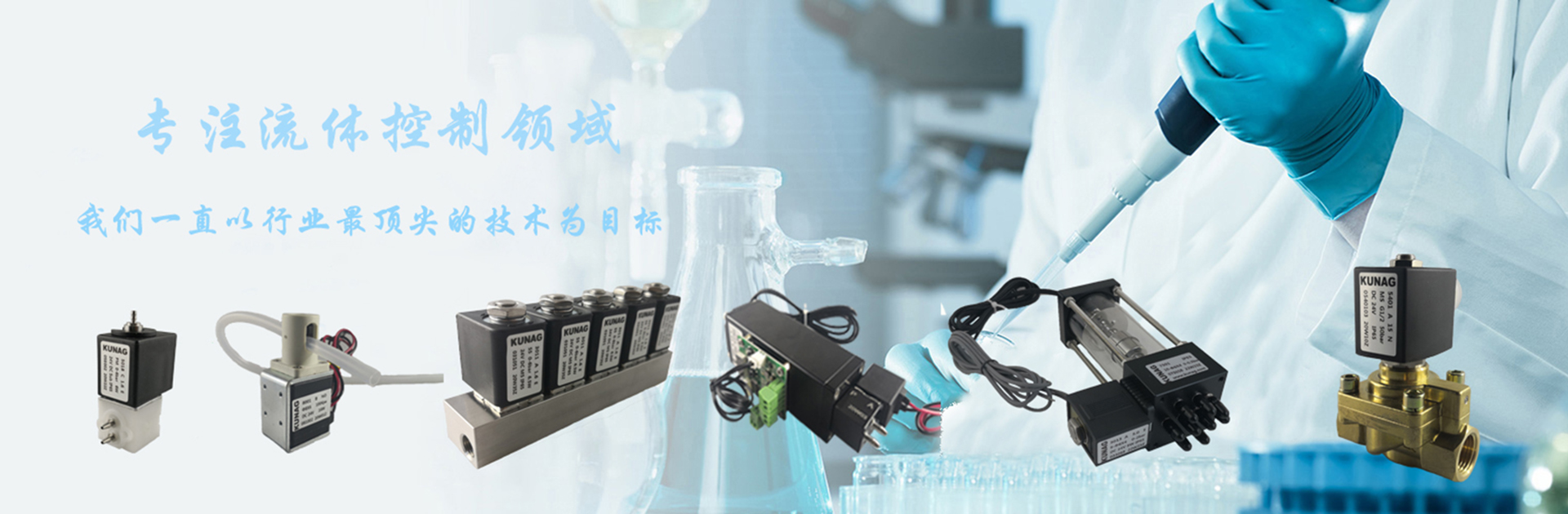
Product Name: Imported Unloading Ball Valve Product Model:
Buhrer
Drive method: manual, electric, pneumatic Connection: flange
Structural form: floating ball, fixed ball Seal structure: PTFE, RPP, Tai alloy, etc.
Pressure range: 1.6MPa-16MPa Nominal dia
meter: DN50-800
Common materials: carbon steel, 304, 316, titanium alloy steel, etc.
Product introduction
The imported ash ball valve produced by Brel can be driven by manual, electric, pneumatic, flanged connection, floating ball, fixed ball, and PTFE, RPP, Tai alloy, etc. in the sealing structure. Pressure range PN1.6MPa-16MPa, nominal dia
meter is DN50-800mm, the material can be selected from carbon steel, 304,316, titanium alloy steel, etc. Because the valve is used in a very wide range, the same valve has different combinations in different situations and working conditions.
Product Details
The imported ash discharge ball valve has a simple structure and good sealing performance. However, the load of the sphere bearing the working medium is transmitted to the outlet seal ring. Therefore, it is necessary to consider whether the seal ring material can withstand the working load of the sphere medium. This structure is widely used in medium and low pressure ball valves.
1. Scope: This manual is applicable to electric (or pneumatic) ball valves at flange connection ends.
2. Composition: It consists of electric (or pneumatic) actuator (20) and ball valve body, and its connection is supported by bracket (18) and connecting shaft (17).
3. Restrictions on use
Temperature and pressure limits
l Display the maximum operating pressure of the ball valve at the maximum and minimum operating temperature.
l Use PTFE or RTFE valve seats and seals, the operating temperature should be between -290C to 2000C. The operating temperatures of other types of valve seats and seals shall be subject to inspection by the KI factory.
l The nominal pressure level (PN) of the valve can indicate the maximum working pressure of the valve under normal temperature conditions. (For example: PN4.0, which indicates that the maximum working pressure at the operating temperature of -290C ~ 380C is 40 Bar (4.0MPa).
l For the precautions of electric or pneumatic actuators, refer to their corresponding instructions.
4. Installation
1. Remove the protective caps on both sides of the flange end, and perform flushing with the valve fully open.
2. Before installation, the whole machine should be tested according to the specified signal (electricity or gas) (to prevent the vibration caused by transportation from affecting the performance), and it can be installed on the line only after being qualified.
3. Before preparing to connect to the pipeline, flush and remove the impurities remaining in the pipeline (these materials may damage the valve seat and ball).
4. During the installation, please do not use the actuator part of the valve as a lifting point to avoid damage to the actuator and accessories. .
5. This type of valve should be installed in the horizontal or vertical direction of the pipeline.
6. The pipeline near the installation point must not have low droop or bear external force. Pipeline brackets or supports can be used to eliminate the deviation of the pipeline.
7. After connecting to the pipe, please cross-tighten the flange connection bolts with the specified torque.
4. Operation and use
1. Make sure that the pipes and valves have been flushed before operation.
2. The operation of the valve drives the rotation of the valve stem according to the input signal of the actuator: When the valve rotates 1/4 turn (900) in the forward direction, the valve closes. When rotated 1/4 turn (900) in reverse, the valve opens.
3. When the direction arrow of the actuator is parallel to the pipeline, the valve is open; when the arrow is perpendicular to the pipeline, the valve is closed.
5. Maintenance
Has a long service life and maintenance-free period, which will depend on several factors: normal working conditions, maintaining a harmonious temperature / pressure ratio, and reasonable corrosion data
Note: When the ball valve is closed, there is still pressurized fluid inside the valve body
前 Remove the line pressure and keep the valve in the open position before maintenance
Before maintenance, disconnect the power or air source
前 Before repairing, lock the actuator and the bracket disengagement part, install the pipeline according to the valve flow direction, and it can be used normally.
Professional manufacturing and professional services, KUNAG creates more value for you
Continuously improving the quality of services and keeping improving, "sincere service" is the eternal theme of KUNAG. Kunag strictly complies with the requirements of ISO9001-2000 quality system certification, strictly controls the quality and responsibilities to the people to ensure the healthy operation of production, sales and service. To strengthen communication with customers and to provide our customers with quality products and perfect service, we hereby make the following commitments:
Product Standards
Products are designed, manufactured, and inspected strictly in accordance with China\'s GB, HG standards, and US API standards. The hardness of the sealing surface meets the national requirements and the width exceeds the national standard.
pre-sale service
Product introduction, technical communication, non-standard product design, troubleshooting.
Sale service
Trustworthy contracts, guarantee timely delivery, and keep in touch with customers at any time.
For special or complex products, our factory arranges technicians to train and guide users on product use, troubleshooting, tuning and maintenance.
After sales service
The warranty period of Weitong products is 12 months from the factory, and the "three guarantees" service (return, replacement, repair) is implemented.
During the use of our products, our factory regularly organizes technical and inspection personnel to visit and solicit user feedback on product quality, use conditions, and improvement opinions in order to further improve product quality.
Quickly respond to customer complaints about product quality problems, and after-sales service personnel rushed to the scene within 24-36 hours (48 hours outside the province).
For after-sales service, users are required to fill in the quality feedback form after the service and make appraisal opinions, while improving Guardian\'s service quality.
 ∷
∷


 KUNAG
KUNAG KUNAG
KUNAG
 KUNAGE